top of page
SURMOD
1930 Hudson Super 8
Driveshaft Rebuild
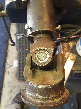
The picture shows the arrangement of the differential, pinion, universal, and driveshaft.
The left portion of the driveshaft is from the Chevy Nova. Then it was welded to a section of the original driveshaft and from there the rest is original.

After going over the car completely I knew that the rear Universal Joint needed replacing. When I had the driveshaft out I packed it with grease and it helped a bit but after driving about 60 miles I decided to face the problem. It meant totally rebuilding the differential end of the driveshaft because there just aren't any 1930 Hudson universal joints out there.
The universal cross and end caps were a bit different in that the cups didn't have any roller bearings in them. They are metal on metal. Not only that but there were no keepers to keep the end caps in place on two of the ends.

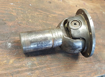

The two pictures above show what the universal assembly looks like without the cover on. The cover is basically a guard to keep most of the road dirt out of the universal joint.


The picture above shows no retaining clip and it appears like the sleeve that goes over the cross is out past the end of the casting of the flange plate.
The picture above shows a circular clip and a slot in the casting but there is no obvious signs as to how to remove that retaining clip.

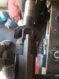
Once I separated the flange portion of the U-Joint assembly I needed to cut off the portions that held the cross piece of the assembly.

This shot was taken after I had cut one side off. The solid portion left was a little concern in that it would potentially create a balance issue. I delt with this later on.
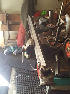
I was fortunate enough to come across 3 complete driveshafts and after examining them and measuring them I decided on the one right behind my driveshaft in the foreground. The outside diameter of the shaft matched the diameter of the raised section where the yokes were in the above pictures.

I cut this portion off the end of the doner driveshaft and it would have been simple and easy to simply weld it on the the flange that I had cut the two yoke sections off of. However I would only have been able to lay a welding bead around the outside.

So I cut a section off the remaining part of the driveshaft that was about 1 1/2" long which gave me the approximant overall length that I needed which I had previously determined.
Doing it this way allowed me to run a bead around the outside as well as around the inside. Plus on the inside I built up numerous welding beads to match the area of the solid thick parts. By doing this it helped even out the amount of weight on the inside for better balance.

This pictures shows the section being aligned with the flange using 3 magnets. However I forgot to take a picture of the inside welding that was done. But pretty much all the dark areas on the inside were filled with weld.
Next I chiseled off the end section of the driveshaft from the splined yoke end.

I then pressed on the new end which included the original flange that matches up to the flange coming off the pinion assembly.

The white arrows shows about where I cut straight through the cars driveshaft.

I made cut #1 first to get the covers and spring off. The smaller diameter round section was solid steel.
Then I made the cut #2 and at that point the larger diameter which was the end of the driveshaft was also solid steel. Both these pieces were discarded.

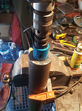
The splined portion of the new end that I welded up was about 1 5/8". The closest hole saw that I could find was 1 3/4". This actually turned out to be an advantage to have a gap between the two.


After drilling about an inch and a quarter the hole saw broke through. After that it was just the thickness of the driveshaft. So there was a sleeve in the end of the shaft but I couldn't determine what was keeping it fixed in place.

Since there was a gap between the outside diameter of the spined shaft that is connected to the new U-Joint and the inside diameter of the drilled out driveshaft, this allowed me to precisely centre the splined shaft by drilling and taping 3 holes equally spaced around the driveshaft.
Once the 3 holes were drilled and taped I threaded in 1/4" bolts to centre the shaft. Using an allan wrench to slip in the gap all the way around. The nice thing about allan wrench is that not only size differences is very little it gets even smaller when you have SAE and metric to choose from. Once I started to screw in the bolts I selected the allan wrench that was extremely close to the gap.

I cut and shaped a piece of angle iron so it will pin point the centre of one of the fixed centre of a U-Joint cap at one end. At the other end I found that the casting was slightly different on the adjacent U-Joint cap centres so I cut another short piece that I can slide out the the right length to see where the centre is. That's where it will be positioned when I weld the inserted splined shaft.
Once I installed the replacement differential assembly I reinstalled the driveshaft and set the end clearance of the splined end that goes into the transmission at about 7/8".
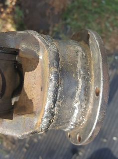

I then ran a second bead of weld on the spacer sleeve at the pinion end of the driveshaft. ( left picture)
Then at the opposite end I ran a triple bead to fill the gap between the shaft and the pinion shaft assembly, which is now at the differential end. I also ran a triple bead of weld around the edge, just to insure that the inner sleeve stayed put. I cut the heads off the three allan positioning bolts and ran a bead of weld to hold them in place and ground them smooth.
bottom of page