top of page

SURMOD
1930 Hudson Super 8
Turn Signals
It was necessary to add turn signals to the car but I wanted them to blend in better than the ones that came with the car when I bought it. The rear turn signals were missing but the holes were cut into the fenders. So for the rear signals I installed a pair of rear lights that I picked up at a swap meet. Not sure what they came off of but they blend in with the shape of the fenders.
The turn signal assembly that I bought is the standard aftermarket style. I painted the 4 way flasher knob black because it was red and it stood out like a sore thumb. I may paint the whole assembly black so it blends in a little better.
The authentic stop light and licence plate bracket had to be moved up about 4 inches to clear the location of the turn signal. I used the original bracketry and mounted it off of the trunk rack as opposed to being mounted off of the rear bumper support.

The front turn signals are actually mid 40's spot lights. I bought about 6 spot light assemblies at a swap meet that were missing lots of parts. However I managed to piece two of them together that matched. I bent the arm at 90% and welded them to the back of the front licence plate brackets.

These spot lights are halogen seal beams. I decided to convert them to just a standard 1156 12V bulb, because of the replacement cost for the seal beams and the difficulty finding them.
I bought a one inch diamond hole saw and after cutting off the two glass protrusions that the contacts used to be attached to, I slowly drilled a hole. Because of the shape around where the contacts used to be I had to tuck the hole up under them. Once the hole was drilled I got all the burnt out pieces out of the seal beam.

I bought a couple 1156 bulbs and a pair of sockets. The style of socket was important because it allows me to pinch the two sides which allows easy in and out movement for getting at the bulb. The other style snaps in place and I felt that the glass was too thick for that and that it might wear down the glass over time.
This style of socket allowed me to easily solder a ground wire to one of the sides that locks the socket in place.
The lip around the socket was a bit too large so I had to grind off a couple spots for it to fit in tight.

The bulb being below the centre point is barely visible and I don't think anyone would even notice it.


Turn Signal Switch Assembly Failure
One minute they were working and the next they weren't. I checked the fuse and it had blown, and when I pulled apart the assembly it was clear what had happened.
The wire going to the indicator bulb had seperated from the end contact that touches the bulb and it had shorted out against the assembly.

The whole assembly isn't designed very well. The wire is only 18 gauge, so it's very small. The end contact that is soldered on to the end of the wire which touches the base of the bulb, is microscopically small.
As you use the turn signals, that wire moves significantly back and forth, which caused the end to break off.
In this picture, between the bulb and the socket, is the end contact that broke off.
I designed a much more substantial end using a tiny machine screw and a modified connector fitting.

I ground off the threads and a little more so it would slip into the end of the modified connector. Then I soldered them together.

This picture shows the new contact end soldered on to the wire before I trimmed it up evenly. Then I slid down the non conductive washer that holds back the spring. (I forgot to slide it down into view for the picture) Then I slid down the heat shrink and heated it up.

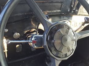
The other issue with this assembly was that when I tightened it really tight to the steering column, the worm screw would skip and not tighten any more. Originally I thought that the worm gear was worn down, but that didn't make too much sense since it was new when I got it and it had only been recently installed. After thinking it through, once again I concluded that it was a poor design. The worm gear catches the outside of the teeth on the clamp. So what happens is that once the clamp is tightened really tight to the steering column the clamp is actually pulled away from the worm gear and that is when it would slip. By design the assembly uses the hose clamp to create a ground. So not only would the assembly be loose, it also had the potential to loose ground.

The clamping method was to have one end of the hose clamp attached to the assembly and the other end looped around the steering column. It was adjusted by turning the end of the worm gear with a screwdriver.

I took out the worm gear and used a complete heavy duty hose clamp through the same part of the assembly. This picture also shows that I ran a ground wire to the actually body of the assembly as well. The pilot wire is also installed and it's function as it moves back and forth, is much more stable now.

I used the hole where you would originally tighten the worm gear, to run the ground wire into the assembly.

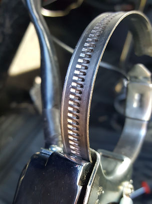
I used a stainless steel, Euro style of hose clamp that is far superior than the regular style.
bottom of page